Chiller Unit Keeps Joint Strike Fighter Pilots Cool A model-based embedded development system enables AMETEK to design, simulate, create firmware for and validate a chiller unit control system.

The Lockheed Martin Joint Strike Fighter (JSF) program aims to deliver affordable, next-generation striker aircraft weapon systems for the U.S. Navy, Air Force, Marines and allies. Currently, the program's Lockheed Martin F-35 Lightning II aircraft are undergoing testing and final development.
There are three versions of the aircraft – one designed for conventional take-off and landing, one for short take-off/vertical landing and a carrier variant. These sophisticated aircraft feature an advanced airframe, autonomic logistics, avionics, propulsion systems, stealth and firepower. Pilots assigned to fly such sophisticated aircraft are subject to high levels of acceleration – up to 9g – and must wear G-suits to prevent blackouts. In fact, pilots, depending on the mission, can potentially wear up to nine layers of clothing.
To prevent pilots suffering from heat stress in the cockpit and on the ground, AMETEK Inc., a leading manufacturer of electronic instruments and electromechanical devices, was contracted to design a portable flight suit chiller unit. This cooling system works with a pilot cooling vest to maintain a pilot's deep body core temperature at ≤ 100.4° F (38° C).
Working under a tight schedule, the company leveraged VisSim™ solutions from Altair Inc. to design an embedded control system for the chiller unit. The VisSim platform enabled the team to build and simulate the plant model, design the entire controller and implement the controller design through rapid prototyping and debugging on the embedded target.
A Cool System
The chiller unit or personal cooling unit (PCU) forms part of the individual cooling equipment, or ICE. Four components comprise the ICE system: a PCU, a Li-ion battery, a battery charger and the fluid charger.
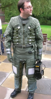 Pilot flight suit with AMETEK's personal cooling unit (PCU)
AMETEK Principal Engineer Kevin Godfrey explains that the PCU interfaces with the cooling vest and delivers the cooling fluid. It uses a vapor cycle cooling circuit and receives fluid from the cooling vest, which transfers the heat load extracted from the pilot.
In the cockpit, the PCU is powered by the aircraft's power supply; the Li-ion battery provides the power to the PCU for ground use and attaches to it for ease of carrying. The battery charger provides the charging profile required by the battery assembly and ensures the correct phase of charging is implemented by monitoring the voltage and current draw taken by the Li-ion battery's cell pack. The fluid charger is designed to operate in a sheltered environment and has a manually operated pump that can fill, pressurize and drain both the PCU and the cooling vest. According to Godfrey, the pilot's vest circulates water glycol, and the chiller unit functions as a mini refrigeration system. "It modulates the temperature of the cool water glycol fluid through piping next to the pilot's skin," he says.
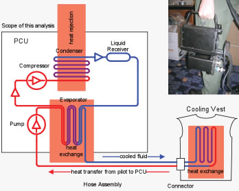
The chiller unit's control system monitors the temperature sensors and motor speed feedback and controls the compressor, expansion valve, and fan pump, as well as regulating the temperature to the pilot. The temperature can vary between 57° F (14° C) to 72° F (22° C.)
Godfrey notes that the system has multiple control loops. One, for example, regulates the fluid-out temperature and the compressor speed to achieve a specific temperature setting. Another control loop monitors the temperature difference over the evaporator and controls the refrigerant flow.
Part of the design challenge is monitoring the various variables and developing the code that goes to the controlling device to make those adjustments automatically. The chiller unit must also run within its power limits to prevent damage.
Model-Based Design
When project development of the chiller unit began, Godfrey and his team had a good idea of what they wanted to develop in terms of hardware. The team decided to use a model-based design approach – leveraging simulation tools to create virtual prototypes and to check that the prototypes worked properly before committing to the design. Godfrey had used VisSim tools previously and believed that its model-based embedded development system, VisSim Embedded, would assist them in development efforts.
As part of the process, the team had to model the plant (the cooling vest and the portable chiller unit) as well as its operations and develop the control system that was to be embedded within the chiller unit.
VisSim Embedded enabled engineers to create a working model of the combined chiller unit and control system via a block diagram approach. They correlated and refined the plant model using measurements of plant responses in the lab. Engineers then built a multi-loop PID controller in VisSim with interlock safety stages that stepped through the start-up and shutdown actions necessary to avoid damage to sensitive device components. This implemented "model-in-the-loop," or MIL, testing.
After engineers debugged and tuned the controller in offline VisSim simulations, they automatically generated ANSI C code from the controller model, compiled and downloaded the code directly to the Texas Instruments (TI) C2000 target chip, using a bi-directional JTAG link (IEEE standard). Engineers tested the control algorithm firmware running on the C2000 by using the VisSim target interface block. It resides in the VisSim plant model running in real time on the PC and uses JTAG technology to easily provide an interface between virtual plant outputs supplied to the firmware and firmware control output supplied back to the virtual plant model in VisSim. This implemented "processor-in-the-loop," or PIL, testing.
When engineers were satisfied with the embedded controller's behavior, they replaced the interactive JTAG input/output (I/O) ports with VisSim blocks for analog-to-digital converter input, general-purpose I/O, pulse-width-modulated (PWM) outputs and custom hardware sensors. Engineers again generated ANSI C code from the controller model, downloaded it to the TI target and ran it against the model simulated in VisSim in real time. At this point in the development process, the controller was electrically connected to the VisSim virtual plant using VisSim/Real-Time PRO to interface to Measurement Computing PCI-based analog and digital I/O PC boards to create analog and digital I/O signals equivalent to the signals from the real plant. This implemented "hardware-in-the-loop," or HIL, testing.
Once that verification level was complete, the controller firmware was run with the actual hardware plant. Each subsystem was vigorously tested employing this established design-simulate-validate procedure.
The testing was also key to adhering to the Safety Evidence Assurance Level (SEAL) standards required by Lockheed Martin. Bi-directional hyperlinks to requirements documents were placed in the VisSim diagram using hyperlink-enabled label blocks. VisSim compound block coloring was employed to track validation progress.
VisSim data export with automatic source diagram and time stamp served as evidence of validation of implementation in meeting the SEAL requirements. VisSim Embedded helped engineers prove that the chiller unit achieved the compulsory safety integrity level through subsystem and whole system testing as well as test result archiving.
A Global Reach
AMETEK, Inc. is a global manufacturer of electronic instrument and electromechanical devices. It has more than 120 manufacturing locations around the world and generated $3.6 billion in sales in 2013.
The company, with a dozen divisions and business units, serves the following markets:
- Aerospace and Defense
- Connectors, Metals and Engineered System & Materials
- Electronic Instruments
- Motors and Blowers
- Power
Efficiency and Quality
According to Godfrey, the team wanted to use a turnkey package in the model-based design process. "We wanted to work in one environment, for the entire tool chain," he says. AMETEK did not want to perform modeling work in one package and then turn it over to a separate coding team to write the C code and then verify it.
Godfrey says, "The VisSim auto code generator allowed me to develop the control algorithm against the model within a simulation environment on the PC – and then take that core control algorithm and put it down on the TI microcontroller unit (MCU) and control the refrigeration system." He notes that the C code generated from VisSim was concise, sharp and targeted.
In addition, VisSim supports a real-time operating system that responds to system events very quickly within the constraints of a control system running in real time. The Visual RTOS provides an "embedded expert," of sorts, when it comes to generating C code for the TI DSP. The TI target incorporates multiple I/O components on a single chip, reducing the size and cost of the final system while increasing its reliability. To develop the C code for each of the peripherals, however, is laborious, as a programmer would have to learn how all of the peripherals work and develop software for their respective applications.
VisSim provides the ability to code for all the peripherals, handling interrupts and scheduling tasks automatically, right from the graphical diagram. With VisSim, AMETEK was able to iterate and optimize the code to be as efficient as possible. According to Godfrey, "It's more critical within an embedded environment with a small processor [to have efficiently generated code] because there are not a lot of extra processor resources. Otherwise, the code would be too big to fit in memory, and the system would run too slowly to control the equipment."
Pleased Pilots
To date, Lockheed Martin has not started formal inflight testing of the chiller unit, but it does have a unit that has undergone general pilot testing. According to Godfrey, the pilots are pleased with the chiller unit and don't want to fly without it.
AMETEK was also pleased with its model-based development process and VisSim's contribution to it. According to Godfrey, "One of the advantages of VisSim is that you are not directly coding in C. You are employing a diagram and using the automatic code generator to create the code." He explains that if the automatically generated code proved too long, for example, he could go back and easily optimize it for efficiency. "VisSim allowed us to model the system and be confident about our design before committing to any hardware," says Godfrey. "The software guided us in the right path to take and sped up development." When it came to the verification and validation exercises, the software allowed code segments to be individually tested and the results logged.
In addition, AMETEK worked closely with the VisSim consulting team, which provided advice on making best use of VisSim to create TI MCU firmware, as well as fielding general support questions.
Moving forward, AMETEK plans to use the model-based development process on other projects. For example, it will leverage its work in embedded processors on an armored fighting vehicle for Spain, an underbelly camera for a Turkish aircraft and a fan control for a Canadian vehicle.
To learn more about VisSim, please visit www.c2rmagazine.com/2015